Predictive sensor guided robotic manipulators.doc
4T焊接滚轮架机械设计【13张图纸】【优秀Word+CAD全套设计】
收藏
资源目录

压缩包内文档预览:(预览前20页/共23页)
编号:447182
类型:共享资源
大小:8.14MB
格式:ZIP
上传时间:2015-07-03
上传人:小***
认证信息
个人认证
林**(实名认证)
福建
IP属地:福建
45
积分
- 关 键 词:
-
焊接
轮架
机械设计
- 资源描述:
-
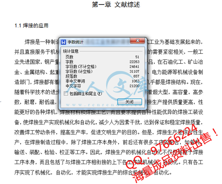
摘 要
焊接装备就是在焊接生产中与焊接工序相配合,有利于实现焊接生产机械化,自动化,有利于提高装配焊接质量,促使焊接生产过程加速进行的各种辅助装置和设备。焊接滚轮架是借助主动滚轮与焊件之间的摩接力带动焊接旋转的变位机械。焊接滚轮架主要用于筒形焊件的装配与焊接。焊接滚轮架按结构形式分为两类:第一类是长轴式滚轮架。第二类是组合式滚轮架。本文主要对组合式4T焊接滚轮架进行设计,并对轴、键等主要构件进行了校核。结果表明各主要部件符合要求。该滚轮架结构简单,使用方便灵活,对焊件的适应性很强。设计中充分的考虑了滚轮架的合理性和经济性等因素。
关键词:焊接;工装夹具;滚轮架
Abstract
Welding equipment is a machine which is used in welding production and welding processes, and it is conducive to welding production mechanization and automation, to improving assembly welding-quality. Then it could prompte to speed up the process of welding production of the various assistive devices and equipment. Welding roller is used initiative and welding pieces of the wheel between the Mount relay driven welding rotating mechanical deformation. Welding roller stands for the main pieces of tube welding and welding assembly. Welding roller standing by structural form is divided into two categories : the first category is long axis-wheel frame., the second category is modular roller frame. In this paper, four pairs of modular T-welded wheel for the design, as well as axial, bond and other main component of checking. The results showed that the main components to meet the requirements. The roller frame structure is simple, flexible, adaptive welded pieces of a strong, which is the most widely used form of the structure. And it could be fully considered the roller frame reasonable and economic, and other factors.
【Key words】:weld, frock clamp, turning rolls
目 录
第一章 文献综述1
1.1焊接的应用1
1.2焊接机械装备1
1.2.1焊接机械设备的分类2
1.2.2焊接机械装备对焊接生产的作用2
1.3焊接自动化:3
1.4焊接工装夹县4
1.4.1焊接工装夹具的特点5
1.4.2焊接工装夹具的分类6
1.4.3对焊接工装夹具的设计要求6
1.4.4焊件在焊接工装夹具中的定位方法7
1.5焊接变位机械8
1.5.1焊接变位机械的分类8
1.5.2焊接变位机械应具备的性能9
1.6几类焊接机械设备的具体介绍10
1.6.1焊接变位机10
1.6.2焊接翻转机11
1.6.3焊接操作机12
1.6.4焊接滚轮架13
1.6.5关于滚轮架轴向窜动的问题16
第二章 方案的选择与确定18
2.1组合式滚轮架的特点:18
2.2滚轮驱动方案20
2.3减速器的选择:20
2.4连轴器的选用:21
2.5滚轮架滚轮的设计21
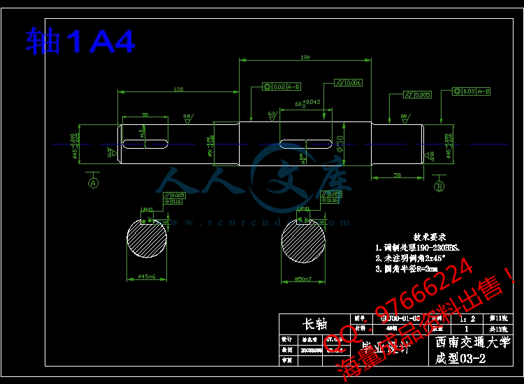
2.6轴的设计23
2.7轴承的选用24
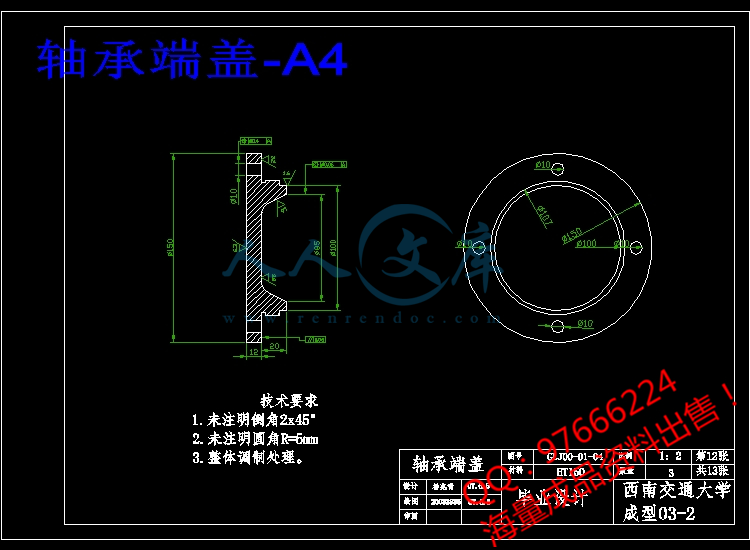
2.8轴承端盖的设计25
2.9丝杠的设计26
2.10键的设计27
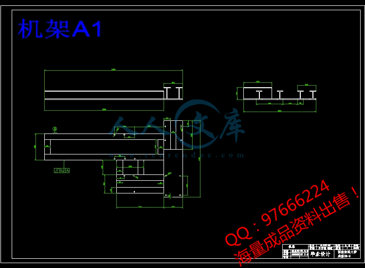
2.11机架的设计27
2.12表面粗糙度29
第三章 计算与校核30
3.1焊接滚轮架的设计计算30
3.1.1驱动圆周力与支反力的分析及中心角的确定30
3.1.2 焊接滚轮架的受力分析33
3.1.3滚轮支反力的计算34
3.2电动机的选定36
3.3轴的校核37
3.4滚轮处键的校核38
3.5轴承寿命计算38
3.6轴承的强度计算39
结论41
致谢42
参考文献43


- 内容简介:
-
Predictive sensor guided robotic manipulators in automated welding cells Adolfo Bauchspiess , a, Sadek C. Absi Alfaro , b and Leszek A. Dobrzanski , c a GRACO/UnB Electrical Engineering Departments, Automation and Control Group, University of Braslia, 70910-900 Braslia, DF, Brazil b GRACO/UnB Mechanical Engineering Departments, Automation and Control Group, University of Braslia, 70910-900 Braslia, DF, Brazil c Silesian University of Technology, Ul.Konarskiego 18a, 44-100 Gliwice, Poland Available online 10 January 2001. Abstract This paper presents an on-line tracking optimization scheme for sensor guided robotic manipulators by associating sensor information, manipulator dynamics and a path generator model. Feedback linearization-decoupling permits the use of linear SISO prediction models for the dynamics of each robot joint. Scene interpretation of CCD-camera images generates spline fitted segments of future trajectory. In the sensor vision field the proposed optimization criteria minimizes the error between state variables of the prediction model and the state variables of the spline trajectory generator. These techniques, allied with separation of disturbance rejection and path-tracking performance by the proposed feed-forward following model predictive (FMP) servo-controller design, permits very high path tracking dynamics (and consequently small errors). Experimental results on implementation of ntsa CCD-camera guided hydraulic robot and a welding robot demonstrates the practical relevance of the proposed approach. Author Keywords: Machine vision; Welding ; Robotic Article Outline 1. Introduction 2. Dynamic system tracking 3. Following model predictive path tracking 4. Problem formulation 5. Calculation of the optimal control sequence 6. Superposition of the minimization horizon 6.1. The receding horizon approach 7. Velocity and acceleration reference 8. Simulation for a typical trajectory 9. Experimental results 10. Circle form test 11. CCD-camera guided weld robot 12. Conclusion Acknowledgements References 1. Introduction Robotic manipulators have been used in welding cells for a long time in order to improve welding quality. Substitution of mancraft in welding ntscells where a robot welds only few different parts every time in the same manner such as in spot welding commonly used in the automobile industry is not a very difficult task. But in a flexible, just-in-time, and CAD customized production approach, very different parts are to be welded demanding an “intelligent” robot -welding concept. Providing robots with abilities of an experienced welder is the visionary target of many research groups. The realization of such ambitious goals leads to the use of sensors which provide the robot with the necessary information, so that it can interact within their environment. Preferentially, the robot should autonomously find and precisely weld metal joining paths in order to fulfill some given manufacturing tasks 1. A shortcut of the use of sensor-guided robots is that due to their mechanical inertia they can react only relatively slowly to changes in the trajectory information captured by the sensor system. In this paper, it will be shown how a sensor that can look ahead such as a CCD-camera can be used to improve substantially the seam tracking precision. The proposed algorithm virtually eliminates the tracking error by considering the dynamic model of the robot and the captured future trajectory information. Incorporating an internal trajectory generator model leads, thus, to the following model predictive servo-controller algorithm (FMP for short 3). Non-linear control techniques 6, 7 and 12 can decouple and linearize robotic manipulator joints. So that each robot joint can be considered as a linear SISO system. Using such a model, the tracking problem of sensor guided manipulators can be treated in the linear domain. In particular, the discrete optimization of the predictive path-tracking problem with the proposed cost function leads to an analytical solution ntswith guaranteed stability 3 and 11. This new approach avoids the typical recursive solution usually employed for the Riccati equation 2. Robotic manipulators equipped with sensors can automate industrial processes in an “intelligent manner”. Those are objects of intense research efforts in the field of artificial intelligence (AI): to build machines that consider the information captured from the surrounding environment in a proper (intelligent) manner. With the support of sensors the working trajectory of the robot can be obtained within a certain vision field which will be used here as the minimization horizon of the tracking error. The proposed algorithm was implemented to control a hydraulic manipulator guided by a CCD-camera where it was shown that the FMP methodology significantly reduces the dynamic tracking error. Currently, this technique is being implemented to control a 6-DOF CCD-camera guided welding robot at GRACO. 2. Dynamic system tracking Depending on the characteristics of tracking the following classification of problems are usual 2: The tracking problem: the reference trajectory is a determined (arbitrary) function of time for 0tT. The servo problem: the system is to be controlled in such a manner that the controlled variable will follow a reference signal from which it is only known that it belongs to a certain signal class, e.g. a sequence of steps or polynoms until a certain order. nts The model following problem: the output of the servo-system should follow the output of a path generator. For sensor-guided robotic manipulators, the tracking problem is to be solved because the captured trajectory is not known a priori. For the model following problem, it is possible to obtain ideal following, i.e. zero tracking error in every time instant 14. A proper path generator for robotic manipulators is an integrator chain which in the case of three chained integrators produce spline polynoms. The scheme to obtain ideal following for a linear SISO system in the controllable canonical form is shown in Fig. 1. Display Full Size version of this image (16K) Fig. 1. Scheme to obtain ideal following 14. Despite ideal following can not be obtained for sensor guided manipulators, their basic idea will be used here: minimize the error between the state variables of the controlled system and the state variables of a path generator internal model. It is important to point out that if the captured trajectory is indeed a spline, the theoretically FMP tracking error will be zero 3 and 14. 3. Following model predictive path tracking Consider the controllable and observable scalar nth order discrete time linear system described by nts x(k+1)=Akx(k)+bkus(k); x(0)=x0, y(k)=ckTx(k) (1) where x(k) is the n1 state vector at time t=kT (T the sampling period), us(k) the input and y(k) the system output. This model, with n=3 will be used here for robotic manipulators that are linearized and decoupled by an underlying non-linear multivariable joint controller. The resulting integrator chain that is obtained, for example, by the inverse system controller 6 and 7 or by the controller of the highest derivative 12 is then transformed in a P Tn system by means of linear state feedback. Finally, the discrete model (1) is obtained using a Step Invariant Transformation 14. That model will be here, therefore, denominated predictor model because it allows the prediction of the dynamic behavior of each robot joint for a given reference trajectory. 4. Problem formulation Given an nth order plant described by (1). The reference trajectory and its derivatives are known from t=(k+1)T until the horizon t=(k+m)T. The current state of the plant is x(k). The position, velocity, acceleration, and higher derivatives of the controlled variable correspond to the states of the system in the controllable canonical form. The problem consists on the calculation of the control sequence us(k),us(k+1), us(k+m1), such that the following predictive path tracking optimization criteria (or cost function) will be minimized: (2) The weighting matrices Qi and R are symmetric positive defined. In the most general case, these matrices can be time dependent. The vector error terms i are nts (3) (4) (5) (6) The searched control sequence is also described by the vector us(k). Each vector error term in (2) embraces a prediction horizon of m samples. The design matrices Qi and R weight the corresponding error terms leading to a scalar cost function J. For diagonal Qi and R, the cost function J reduces to a weighted sum of quadratic errors that penalizes reference deviations in each state space variable (i.e. position, velocity, acceleration, and so on) over the known m future sampling times. As will be shown later, choice of the elements in Qi and R (this is thus the design procedure) establishes a particular dynamic behavior of a FMP servo-controlled system. The last vector term (k), the control variable displacement stands in the cost function for energy limitation. It constrains the control signal us(k) in the vicinity of the actual set point w(k). It can be assumed, without loss of generality that the gain of the linearized scalar system (1) is unitary (in steady-state us(k)=w(k). In the literature 13, control signal limitation is also considered using for plants with integrating characteristic and by otherwise. ntsThe proposed predictive path tracking optimization criteria (2) not only minimizes the average deviation between controlled variable y(k) and reference signal w(k) considering energy limitation as usual in most predictive algorithms 8 and 13, but generalizes, considering all information available: (1) the state space variables of the controlled system, (2) the future trajectory captured in the sensor vision field, and (3) the state-space variables of a trajectory generator model. The proposed use of “all information” can even supply a great lack in the predictive control theory: guaranteed closed loop stability 3 and 11. Indeed 11 shows the equivalence of the proposed FMP algorithm to a discrete version of the Riccati LQ-controller which as observed by Kalman 2 is closed loop stable. 5. Calculation of the optimal control sequence Beginning with the state-space system description (1), it is possible to predict the system “output” vectors comprising the time points t=k+1 up to t=k+m. The following relations can be given: (7) The matrices G, H, with =0,1, n1, are given by Using (3), (4), (5) and (6), we express the criterion J as a function of This equation has, with exception of the searched control sequence, only known variables. So, from that equation we can calculate the searched control sequence us(k) by setting the vector of ntsthe partial derivatives J/us(k) to zero to obtain from which we obtain the following result: (8) With exception of the not allowed case Qi=R=0, the inverse matrix exists. To apply this algorithm to robotic manipulators, it will be assumed that an underlying non-linear joint control scheme is being used which decouple and linearize each robot joint. The dynamic of each joint will be considered as P T3. Consequently the FMP servocontroller will be designed for such SISO systems. The control sequence (8) can be interpreted as a linear, periodic (with period mTs) time-variant pre-filtering of the reference vectors with a linear state feedback also time-variant. This can be better recognized in the following reformulation of (8) for a third-order system: (9) where are matrices of order mm, and Mx the matrix of order m3. Observing each line of this vector equation it can be seen that the control signal us(k+v), i.e. the signal in the time point v in the minimizing horizon k, k+m1, is dependent on system state in the starting instant of the minimization x(k) and from all reference trajectory values in that minimization horizon ( ). The computation of the control sequence using (9) is not convenient. In the following, it will be shown that some simplifications can be made without relevant prejudice of precision on path tracking. 6. Superposition of the minimization horizon ntsThe superposition of the minimization horizon, the so called “receding horizon”, reduces the error in the transition between segments and has the advantage, relevant in terms of control quality that disturbances are recognized much earlier, and can so be compensated in the next minimization. If the computed m signals were used, disturbances that occur in the segment could be considered only in the next computation 3. 6.1. The receding horizon approach The control law for the new minimization after each step can be obtained from the complete minimization over m steps using just the first value of the computed sequence (10) This control signal corresponds to the use of the first row of vector Eq. (9) (11) or more explicitly (12) 7. Velocity and acceleration reference Usually, when guiding a robotic manipulator by sensors only position reference is available (is captured), velocity and acceleration must be computed from samples of the position reference. One possibility is to use a numerical differentiation. Another possibility is the use of coefficients of interpolating polynoms 3. A suitable numerical approximation for the reference velocity and acceleration is given by 4 nts with a residual error of Ow5 and Ow6, respectively. These equations guarantee a good approximation when w(5), w(6), are small. Greater errors can occur only in points where the trajectory have a discontinuity. Incorporating the numerical differentiation to the input filter, results in a compact form for the FMP control law, Eq. (13) which can be visualized by the block-diagram in Fig. 2. (13) Display Full Size version of this image (5K) Fig. 2. The FMP Servocontroller. 8. Simulation for a typical trajectory The simulation of the FMP servo-control for a linearized robot joint described by and a typical trajectory is shown in Fig. 3. The reference signal w and the output of the plant y are almost identical as seen in Fig. 2a. The small residual error can be seen in Fig. 2d. As expected in the vicinity of reference velocity discontinuities occurs a greater error. nts Display Full Size version of this image (7K) Fig. 3. Simulation of FMP servocontroller. When only the non-linear decoupling controller with state-space feedback is used (system described by (1) we have a pronounced tracking error, Fig. 3c. Fig. 3b shows that the FMP servo-controller produces a control signal that “foresees” (predict) the plant lag dynamics, so enabling the minimization of the trajectory error. 9. Experimental results The industrial automation has experienced a fast evolution due to the great development of digital techniques. An adequate mathematical apparatus combined with powerful digital processing equipment permits nowadays control complex tasks, e.g. hydraulic driven robotic manipulators with the precision demanded by the manufacturing industry 5. These, which for a long time had been considered as “very difficult” to be controlled because of their ex tremely non-linear characteristics have newly attracted research interest. The great power density of the hydraulic drive leads to very advantageous robot weight-load ratio (typically 1:5 when electrical driven robots have a ratio of approximately 1:100). The implemented control scheme, Fig. 3, shows the FMP controller as a feed-forward channel, that allows separation of path tracking and disturbance rejection characteristics. The slower non-linear and state-space control of the robot is designed for disturbance rejection while the reference tracking is enhanced by the fast predictive dynamic ntsof the FMP controller. As a stable system by itself, the feed-forward FMP filter will not affect the stability robot joint control scheme ( Fig. 4). Display Full Size version of this image (15K) Fig. 4. The FMP control of CCD guided robot. To verify the theoretical FMP algorithm results, a hydraulic manipulator guided by a CCD-video camera 3, 9 and 11 as shown in Fig. 5 was used. Display Full Size version of this image (22K) Fig. 5. Hydraulic manipulator guided by a CCD-camera. The trajectory to be followed by the robot was printed on paper and attached to the trajectory panel. After finding an border the control scheme guides the robot along this border with a pre-established TCP velocity (Fig. 6). nts Display Full Size version of this image (7K) Fig. 6. Schematic description of the experimental assembly. The non-linear decoupling controller was implemented on an AT&T DSP32C processor in a PC host. Two DSP16A and a DSP32C in another PC host carried out the image interpretation and the FMP servocontrol. A monochrome DALSA Inc. 128128 pixel camera, with 16 MHz dot clock, required the project of a custom high-speed frame-grabber as illustrated in Fig. 7. Display Full Size version of this image (3K) Fig. 7. Schematic description of the experimental assembly. A typical image of the implemented frame-grabber is shown in Fig. 8. Display Full Size version of this image (11K) Fig. 8. Typical CCD captured trajectory. From each image, 10 border points in tracking direction are extracted. After a path length parameterization and a transformation in joint ntscoordinates, a spline fitting is employed. This analytical spline is sampled to furnish new trajectory points to the FMP as suggested in Fig. 5. 10. Circle form test For characterization of positioning precision and repeatability of working machines and industrial manipulators, the circle form test is frequently used 10. By this test, the joints are so moved that couplings and friction effects, particularly for slow motions can be evidenced. Fig. 9 presents measures for the circle form test for the CCD-guided
- 温馨提示:
1: 本站所有资源如无特殊说明,都需要本地电脑安装OFFICE2007和PDF阅读器。图纸软件为CAD,CAXA,PROE,UG,SolidWorks等.压缩文件请下载最新的WinRAR软件解压。
2: 本站的文档不包含任何第三方提供的附件图纸等,如果需要附件,请联系上传者。文件的所有权益归上传用户所有。
3.本站RAR压缩包中若带图纸,网页内容里面会有图纸预览,若没有图纸预览就没有图纸。
4. 未经权益所有人同意不得将文件中的内容挪作商业或盈利用途。
5. 人人文库网仅提供信息存储空间,仅对用户上传内容的表现方式做保护处理,对用户上传分享的文档内容本身不做任何修改或编辑,并不能对任何下载内容负责。
6. 下载文件中如有侵权或不适当内容,请与我们联系,我们立即纠正。
7. 本站不保证下载资源的准确性、安全性和完整性, 同时也不承担用户因使用这些下载资源对自己和他人造成任何形式的伤害或损失。

人人文库网所有资源均是用户自行上传分享,仅供网友学习交流,未经上传用户书面授权,请勿作他用。
|
2:不支持迅雷下载,请使用浏览器下载
3:不支持QQ浏览器下载,请用其他浏览器
4:下载后的文档和图纸-无水印
5:文档经过压缩,下载后原文更清晰
|
 川公网安备: 51019002004831号