4T焊接滚轮架机械设计【13张图纸】【优秀Word+CAD全套设计】
收藏
资源目录

压缩包内文档预览:
编号:447182
类型:共享资源
大小:8.14MB
格式:ZIP
上传时间:2015-07-03
上传人:小***
认证信息
个人认证
林**(实名认证)
福建
IP属地:福建
45
积分
- 关 键 词:
-
焊接
轮架
机械设计
- 资源描述:
-
摘 要
焊接装备就是在焊接生产中与焊接工序相配合,有利于实现焊接生产机械化,自动化,有利于提高装配焊接质量,促使焊接生产过程加速进行的各种辅助装置和设备。焊接滚轮架是借助主动滚轮与焊件之间的摩接力带动焊接旋转的变位机械。焊接滚轮架主要用于筒形焊件的装配与焊接。焊接滚轮架按结构形式分为两类:第一类是长轴式滚轮架。第二类是组合式滚轮架。本文主要对组合式4T焊接滚轮架进行设计,并对轴、键等主要构件进行了校核。结果表明各主要部件符合要求。该滚轮架结构简单,使用方便灵活,对焊件的适应性很强。设计中充分的考虑了滚轮架的合理性和经济性等因素。
关键词:焊接;工装夹具;滚轮架
Abstract
Welding equipment is a machine which is used in welding production and welding processes, and it is conducive to welding production mechanization and automation, to improving assembly welding-quality. Then it could prompte to speed up the process of welding production of the various assistive devices and equipment. Welding roller is used initiative and welding pieces of the wheel between the Mount relay driven welding rotating mechanical deformation. Welding roller stands for the main pieces of tube welding and welding assembly. Welding roller standing by structural form is divided into two categories : the first category is long axis-wheel frame., the second category is modular roller frame. In this paper, four pairs of modular T-welded wheel for the design, as well as axial, bond and other main component of checking. The results showed that the main components to meet the requirements. The roller frame structure is simple, flexible, adaptive welded pieces of a strong, which is the most widely used form of the structure. And it could be fully considered the roller frame reasonable and economic, and other factors.
【Key words】:weld, frock clamp, turning rolls
目 录
第一章 文献综述1
1.1焊接的应用1
1.2焊接机械装备1
1.2.1焊接机械设备的分类2
1.2.2焊接机械装备对焊接生产的作用2
1.3焊接自动化:3
1.4焊接工装夹县4
1.4.1焊接工装夹具的特点5
1.4.2焊接工装夹具的分类6
1.4.3对焊接工装夹具的设计要求6
1.4.4焊件在焊接工装夹具中的定位方法7
1.5焊接变位机械8
1.5.1焊接变位机械的分类8
1.5.2焊接变位机械应具备的性能9
1.6几类焊接机械设备的具体介绍10
1.6.1焊接变位机10
1.6.2焊接翻转机11
1.6.3焊接操作机12
1.6.4焊接滚轮架13
1.6.5关于滚轮架轴向窜动的问题16
第二章 方案的选择与确定18
2.1组合式滚轮架的特点:18
2.2滚轮驱动方案20
2.3减速器的选择:20
2.4连轴器的选用:21
2.5滚轮架滚轮的设计21
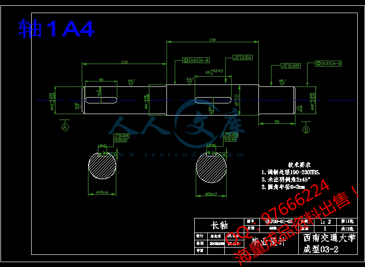
2.6轴的设计23
2.7轴承的选用24
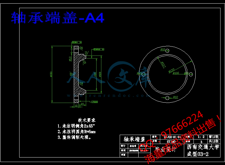
2.8轴承端盖的设计25
2.9丝杠的设计26
2.10键的设计27
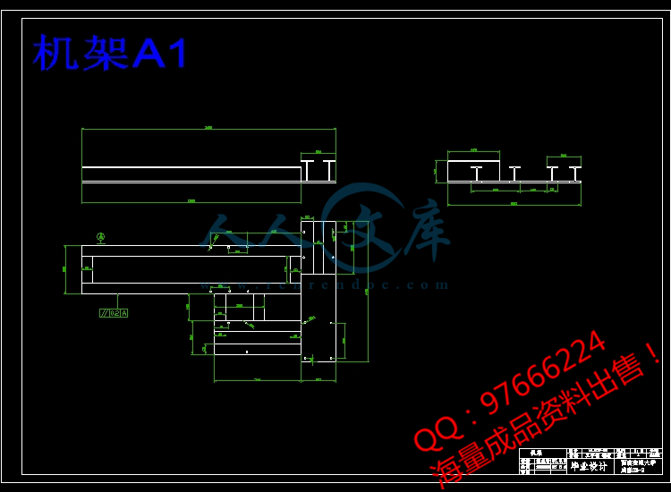
2.11机架的设计27
2.12表面粗糙度29
第三章 计算与校核30
3.1焊接滚轮架的设计计算30
3.1.1驱动圆周力与支反力的分析及中心角的确定30
3.1.2 焊接滚轮架的受力分析33
3.1.3滚轮支反力的计算34
3.2电动机的选定36
3.3轴的校核37
3.4滚轮处键的校核38
3.5轴承寿命计算38
3.6轴承的强度计算39
结论41
致谢42
参考文献43


- 内容简介:
-
ucfion, the assembly and circular seam welding of rotary workpieces, such as a boiler, a petro- vessel and so on, are conducted on ;i welding roller bed. When ifOtiNtitky On a welding roller bed. the cylinder will inevitably produce axial dl-ifting due to manufacturing, assembling tolerance ot” the welding roller bed and the cylinders surface irrcgtjlalty (divcrgiug from an ideal rotary workpiece), thus the welding procedure may rmt be carried out successfully. It is necessary, thcc- fore, to study the mechanism of the axial drifting of the cylinder to solve the problem of the axial drifting of the cylinder in circumferential welding. The results of the research will benefjt the studying and designing of nnti- drifting welding roller bed. especially the analysis of the applied forces on the bed, and lead to determining the manufacturing and assembling tolerance of the bed, and providing the basis of theory for the mechanical adjusting mode to avoid axial drifting, the adjusting mode of closed circuit in the control circuit, and the selection of the ad- justing value. 2. Theoretical analysis 2. I. Wevelding roller bed and cylinder A welding roller bed is generally composed of four rollers. Driven by the driving roller, the cylinder makes a rotary uniform motion around its axis(shown in Fig. I), during which the circumferential welding procedure is carried outtl. In Fig.1, co is the central angle, S is the supportirg distance, I, is the span of the roller. and V, is the circular linear velocity of the cylinder, also named the 0924-0136/97/$15.00 6%) 1997 Elswier Science S.k All ri* reserved PII SO924-0136(96)02743-4 The axis of the cylinder will be not parallel to thaw of a roller if the roller is deflected by a certain angle from the ideal position, or if the centers of the four rollers lie in the vertices of a simple quadrilateral, or if the centers of the four rollers are not on the same plane, or if the circu- larity of the cylinder is irregular because of deviation in manufacturing and assembling. Thus. the cylinder will inevitably move along its axis when rotating on a bed The contact of the cylinder and a roller can be cansidered as point contact if cytinders axis and rollers axis do not lie in the same plane. Suppose P is the point of contact. The cylinders normal plane A is defined by the plane on which are the cylinders axis and eaeratrix IP across the point of tangency on the cylinder (shown in a cylinders tangent plane E across point P. Thus, plane A is vertical to plane &. I, is a cylinders tangent acrOss P. and lies in plane B. I, is the rollers tangent across the same point P, and lies in plane B also. In general, 0 k ntsdefined as the axial deviation angle between the rol!ers axis and the cylinders axis; p is defined as the spiral angle between generatrix 8 and JJJ . a projective line obtained by projecting the rollers generatris II? across point I on plane H. and y is defined as the projective angle between JJ and JJI- , a projective line obtained by projecting JJJ on plane A. Fig. 5 indicates that the rela- tionship amongst the three angles is tan. p = tan 8 - tan y In Fig. 3, SB, Se and S, are called the spiral displace- ment vector, the axial deviation displacement vector and the projective displacement vector respectively. their relationship being: q$=$+s; Fig. 2 Geometric relationship bej. een the cylinder and an individual roller Fig. 3 Relationship hctwcen the ;rnglc vector and the displacement vector ,. i. 2. #C/trti* CJXid JJJOti0JJ.S JdiJtiOlJShi (1) Spiral motion Rolier Cylinder Fig. 4 Component of axial velocity Because the rollers axis is not parallel to the cylin- ders central line, there is a spiral angle p between /,. and 1, on the point of contact (shown in Fig. 2). When the roller and cylinder rotate synchronistically around their own axes, driven by tangential frictional force. a spiral effect will occur because of the different linear velocity direction between the roller and the cylinder at point P of contact The cylinder has a component of axial velocity, 1: (shown in Fig 4). pi PO, = 1,: . tan /I, where I, is the circular linear velocity of the cylinder. lzfis the cylinders axial component velociry exerted b) a single roller, and j can be 1. 2, 3, 4, representing the four rollers, respectively. (2) Elastic sliding Because of the existence of a spiral angle, an axial force Faj acts on cylinder. When the force IS less than the maximum axial frictional force fNj (whereI is the friction factor, and Ni is the normal pressure between a single roller and the cylinder), the cylinder will slide elastically over the roller along the axial directioni2“1. The compo- nent of the sliding velocity is. eF,V, va;: = - I where e is the elastic sliding factor for metallic roller. e=O.OOl - 0.005. (3) Frictional sliding When F.j is greater than the maximum frictional force fNj, the cylinder will make a frictional sliding over the roller. The sliding resistance is fNj”I. The component of the frictional sliding velocity on Cylinder is Vi;, the magnitude and direction of which can be determined by the universal relationship between the cylinder and the four rollers Frictional sliding will lead to the wear and tear of the surface of the cylinder and the rollers. which is unexpected in welding production When the cylinder drifts, ahovc three kinds of motion do not occur simultaneously Ihereforc. the axial drifting velocity ot the cylinder is no1 the algebraic sum of the three components of vclociry In the case of elastic slid- ing, the axial velocity is. VW. = y; -I- i$ whils! in the case of frictional sliding, the axial velocity is 2.3.1. Axial COJJJJalibk JJJCJtiOtJ Under ideal conditions, when spiral angles fij between the cylinder and the four rollers are all the same, that is: the cylinder will move with compatible spiral motion. Two categories can be classified to analyze the axial mo- tion of the cylinder: (I) When there does not exist an axial component due to gravity. the cylinders axial drifting velocity is: (2) When there exists an axial component of gravity G, there exists an axial force on the cylinder. Now, the axial forces exerted on the four rollers have the same direction ntsespecially, when ,L?=O: In general. spiral angles p, between th cylinder and the four rollers are not equal to each otlwr in size and direction. i e. the geometric relationships between the cylinder and the four rollers are ali inconsislent Thcrc*- fore, the compowepts of the cylinders axial velocity against four rollers (i.e iYC .ta ,) are not identtcal to each another. The cylinder move with axial non- compatible motion The axial velocities of the cylinder againsa the four rollers should be the same because the cylinder is consid- ered as a rigid body as a whols and it has o velocity. However. for some roller, VC . tM cylinders real axial velocity are nat likely to be the same, so an axial frictional force almost certainly appears be- tween this roller and the cylinder The following two categories can be classified to discuss the non-compatible axial motion of the cylinder according to Ihe frictional forces magnitude: (I) When the axial frictional forces erected by each roller and the cylinder are ali less than the mahimuni axial frictional force, :hc action of the cylinder against the rollers produces elastic sliding The axial motion between an individual roller and Ihe cylinder is coordinated hv their elastic sliding when the axial velocity of the cylinder is c.onstant, the algebraic sum of cylinders axial forces erected !y four rollers should be zero if rhe axial component of gravity is ignored. i.e.: 1 c Fj = 0 )=I and there is little difference amongst N, against the foul rollers, so that they can be approximately regarded as the same. Thus: FIIJ =o according to the above two equations, the axial drifting velocity of the cylinder is. (2) When the axial frictional force erected by some roller and the cylinder is greater than the maximum axial frictional force, frictional sliding occurs between the cylinder and this roller Then. the maximum axial force ig acting on the bearing of the roller, its value being Because of the esistence of this frictional sliding. the axial motion between an individual roller and rhe cylinder is not coordinated by their elastic sliding Now the axial non-compatible motion of the cylinder is determined b) the relative relationships between the cylinder and the four rollers. It is difficult to write a general compatible equation of the cylinders axial drifting velocity because this kind of condition is very complex. The following is further analysis and discussion of the problem At first, for ease in analyzing problem, the spiral angle average is defined as and the relative spiral angle as .P: = P, -a Arrange ,L?l in the order from his to smll and thm f1onl posirive to negative, expressed as /J(j). then Similarly, the normal force between the cylinder and a roller can h: expressed as N(j). and the axial force ;I WI :l;Ci) In general, the axial motion of the cylinder dcter- - mined by the spiral angle avcragep is dcfinwl as the compatible component uf the axial motion, i:s velocity being. The axial motion of the cylinder determined by the rcla- tive spiral angle /3(i) is defined as the non-compatible component of axial motion, iis velocity being expressed as r; Analysis shows that y:is determined by the equilibrium condition I the four rollers axial furces when the cylinder moves along axial direction at a con- stant velocity. where not taking into account of the func- lion of gravitys axial component. Supposing tnat the cylinder makes a non-compatible component of axial motion with the maximum relative spiral angle j?(I). its velocity is Jfy = v,. . tan p( 1) then the four axial forces can not be in equilibrium, i e F(l) - /F(2) + F(J) + r;(J) J 0 Therefore, the cylinder can only be approximately con- sidered as making a non-compatible component of axial motion with the second or third relative spiral angle, i.e.: If N(I) + N(2) N(3) + N(J) y,” = v, + tanp(2) or: If N(I) + N(2) I I, When the number of driven rollers deflecred is varted, the degree of the cylinders non-compatible axial motion will be changed. With the incremenr of the number of lollers dellected by Ihe same spiral angle. the compatible component becomes greater, but the non-compatible component becomes smaller. In other words, the cylin- ders axial motion will be transformed from non- compatible motion to compatible motion. Thus, V# be- comes greater also, ultimately, being equal to the com- patible axial velocity determined by the spiral angle p Now. the four rollers have the same spiral anyle fl. SO that V, is: Deflecting driven roller No 4 to a spiral angle of +2” from the equilibrium position, the cylinder will suffer axial drifting, Fig. 8 shows the lC,-LC curve, which latter indicates that V, is directly proportional to L=, the slope of the curve being approximately O.QOiOB. Eecause /?,=+2” is too small, the cylinder does not make frictional sliding against each roller. Thus, the rela- tive axial motion between the roller and the cylinder is completely coordinated by their elastic sliding, so that I;, is- ntsi.e: I, is directly proportional to 1“ For the theoretical curve, the slope K * can be calculated by the following equation K”=+p, = $tan2=z0.00873 where K=O.O0708mm/s in the experimental curve. Thus, in taking account of the experimental tolerance, the two slopes can be considered to be approximately equal. 25 f Fig. 8 Experimental curve of V,-I, 4 Conclusiuns I Because of the dcviaions due to manufacturing and assembling. the cylinders central line and the rollers asis arc nol parallel. i c , tlrcy nrc ilot in the same plane, and thcrc is a spiral angle 11 at hc point of con- tacl between the cylinder and lhe roller in the circular linear velocity direction. The wistoncc of /? is the ba- sic reason fw the occurrence uf axial drifting. The ef- t&t of gravity in cylinders axial direction is also one of reasons tdr drifting. 2. The relative axial motions between an individual roller and the cylinder are composed of spiral motion. elastic sliding and frictional sliding When axial frictional slid- ing does not occur between the cylinder and a single roller, the relative axial motion between the rollers and the cylinder is completely coordinated by their elastic 4 sliding, I, is directly proportional IO &i tan p , J-I When axial frictional slidins occurs between the cylin- der and a roller. the relative asial motion between the rollers and the cylinder will be commonly coordinated by elastic sliding and frictional sliding. but I., is not directly proportional to r;&lllp, J=I The axial motions of the cylinder can be divided into compatible and
- 温馨提示:
1: 本站所有资源如无特殊说明,都需要本地电脑安装OFFICE2007和PDF阅读器。图纸软件为CAD,CAXA,PROE,UG,SolidWorks等.压缩文件请下载最新的WinRAR软件解压。
2: 本站的文档不包含任何第三方提供的附件图纸等,如果需要附件,请联系上传者。文件的所有权益归上传用户所有。
3.本站RAR压缩包中若带图纸,网页内容里面会有图纸预览,若没有图纸预览就没有图纸。
4. 未经权益所有人同意不得将文件中的内容挪作商业或盈利用途。
5. 人人文库网仅提供信息存储空间,仅对用户上传内容的表现方式做保护处理,对用户上传分享的文档内容本身不做任何修改或编辑,并不能对任何下载内容负责。
6. 下载文件中如有侵权或不适当内容,请与我们联系,我们立即纠正。
7. 本站不保证下载资源的准确性、安全性和完整性, 同时也不承担用户因使用这些下载资源对自己和他人造成任何形式的伤害或损失。

人人文库网所有资源均是用户自行上传分享,仅供网友学习交流,未经上传用户书面授权,请勿作他用。
 川公网安备: 51019002004831号