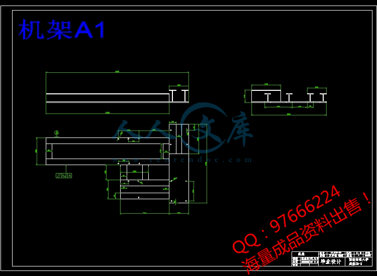
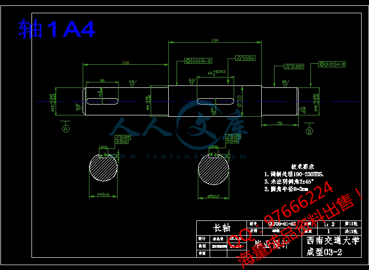
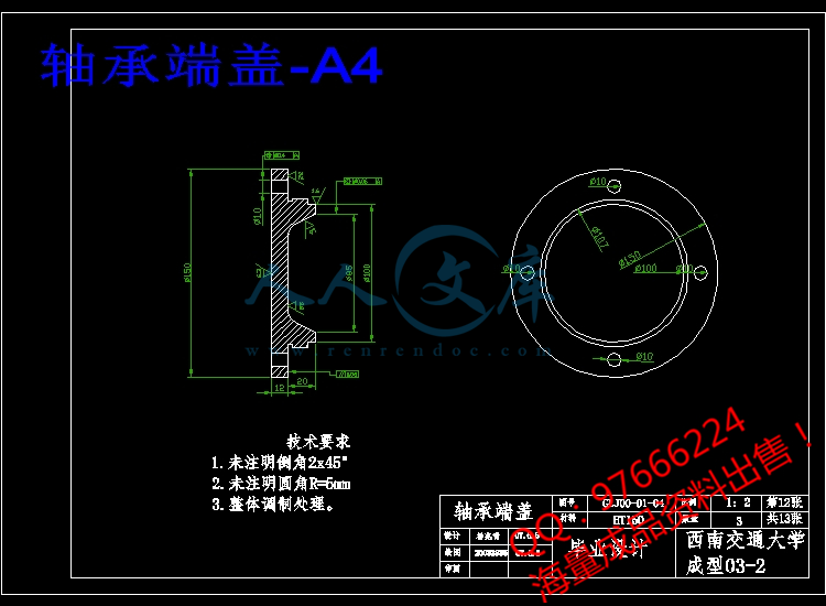
4T焊接滚轮架机械设计【13张图纸】【优秀Word+CAD全套设计】
收藏
资源目录

压缩包内文档预览:
编号:447182
类型:共享资源
大小:8.14MB
格式:ZIP
上传时间:2015-07-03
上传人:小***
认证信息
个人认证
林**(实名认证)
福建
IP属地:福建
45
积分
- 关 键 词:
-
焊接
轮架
机械设计
- 资源描述:
-
摘 要
焊接装备就是在焊接生产中与焊接工序相配合,有利于实现焊接生产机械化,自动化,有利于提高装配焊接质量,促使焊接生产过程加速进行的各种辅助装置和设备。焊接滚轮架是借助主动滚轮与焊件之间的摩接力带动焊接旋转的变位机械。焊接滚轮架主要用于筒形焊件的装配与焊接。焊接滚轮架按结构形式分为两类:第一类是长轴式滚轮架。第二类是组合式滚轮架。本文主要对组合式4T焊接滚轮架进行设计,并对轴、键等主要构件进行了校核。结果表明各主要部件符合要求。该滚轮架结构简单,使用方便灵活,对焊件的适应性很强。设计中充分的考虑了滚轮架的合理性和经济性等因素。
关键词:焊接;工装夹具;滚轮架
Abstract
Welding equipment is a machine which is used in welding production and welding processes, and it is conducive to welding production mechanization and automation, to improving assembly welding-quality. Then it could prompte to speed up the process of welding production of the various assistive devices and equipment. Welding roller is used initiative and welding pieces of the wheel between the Mount relay driven welding rotating mechanical deformation. Welding roller stands for the main pieces of tube welding and welding assembly. Welding roller standing by structural form is divided into two categories : the first category is long axis-wheel frame., the second category is modular roller frame. In this paper, four pairs of modular T-welded wheel for the design, as well as axial, bond and other main component of checking. The results showed that the main components to meet the requirements. The roller frame structure is simple, flexible, adaptive welded pieces of a strong, which is the most widely used form of the structure. And it could be fully considered the roller frame reasonable and economic, and other factors.
【Key words】:weld, frock clamp, turning rolls
目 录
第一章 文献综述1
1.1焊接的应用1
1.2焊接机械装备1
1.2.1焊接机械设备的分类2
1.2.2焊接机械装备对焊接生产的作用2
1.3焊接自动化:3
1.4焊接工装夹县4
1.4.1焊接工装夹具的特点5
1.4.2焊接工装夹具的分类6
1.4.3对焊接工装夹具的设计要求6
1.4.4焊件在焊接工装夹具中的定位方法7
1.5焊接变位机械8
1.5.1焊接变位机械的分类8
1.5.2焊接变位机械应具备的性能9
1.6几类焊接机械设备的具体介绍10
1.6.1焊接变位机10
1.6.2焊接翻转机11
1.6.3焊接操作机12
1.6.4焊接滚轮架13
1.6.5关于滚轮架轴向窜动的问题16
第二章 方案的选择与确定18
2.1组合式滚轮架的特点:18
2.2滚轮驱动方案20
2.3减速器的选择:20
2.4连轴器的选用:21
2.5滚轮架滚轮的设计21
2.6轴的设计23
2.7轴承的选用24
2.8轴承端盖的设计25
2.9丝杠的设计26
2.10键的设计27
2.11机架的设计27
2.12表面粗糙度29
第三章 计算与校核30
3.1焊接滚轮架的设计计算30
3.1.1驱动圆周力与支反力的分析及中心角的确定30
3.1.2 焊接滚轮架的受力分析33
3.1.3滚轮支反力的计算34
3.2电动机的选定36
3.3轴的校核37
3.4滚轮处键的校核38
3.5轴承寿命计算38
3.6轴承的强度计算39
结论41
致谢42
参考文献43


- 内容简介:
-
CE 405: Design of Steel Structures Prof. Dr. A. Varma 1 CHAPTER 6. WELDED CONNECTIONS 6.1 INTRODUCTORY CONCEPTS Structural welding is a process by which the parts that are to be connected are heated and fused, with supplementary molten metal at the joint. A relatively small depth of material will become molten, and upon cooling, the structural steel and weld metal will act as one continuous part where they are joined. Fi l l e t w e l dFi l l e t w e l dntsCE 405: Design of Steel Structures Prof. Dr. A. Varma 2 The additional metal is deposited from a special electrode, which is part of the electric circuit that includes the connected part. In the shielded metal arc welding (SMAW) process, current arcs across a gap between the electrode and the base metal, heating the connected parts and depositing part of the electrode into the molten base metal. A special coating on the electrode vaporizes and forms a protective gaseous shield, preventing the molten weld metal from oxidizing before it solidifies. The electrode is moved across the joint, and a weld bead is deposited, its size depending on the rate of travel of the electrode. As the weld cools, impurities rise to the surface, forming a coating called slag that must be removed before the member is painted or another pass is made with the electrode. Shielded metal arc welding is usually done manually and is the process universally used for field welds. For shop welding, an automatic or semi automatic process is usually used. Foremost among these is the submerged arc welding (SAW), In this process, the end of the electrode and the arc are submerged in a granular flux that melts and forms a gaseous shield. There is more penetration into the base metal than with shielded metal arc welding, and higher strength results. Other commonly used processes for shop welding are gas shielded metal arc, flux cored arc, and electro-slag welding. Quality control of welded connections is particularly difficult, because defects below the surface, or even minor flaws at the surface, will escape visual detection. Welders must be ntsCE 405: Design of Steel Structures Prof. Dr. A. Varma 3 properly certified, and for critical work, special inspection techniques such as radiography or ultrasonic testing must be used. The two most common types of welds are the fillet weld and the groove weld. Fillet weld examples: lap joint fillet welds placed in the corner formed by two plates Tee joint fillet welds placed at the intersection of two plates. Groove welds deposited in a gap or groove between two parts to be connected e.g., butt, tee, and corner joints with beveled (prepared) edges Partial penetration groove welds can be made from one or both sides with or without edge preparation. 6.2 Design of Welded Connections Fillet welds are most common and used in all structures. Weld sizes are specified in 1/16 in. increments A fillet weld can be loaded in any direction in shear, compression, or tension. However, it always fails in shear. ntsCE 405: Design of Steel Structures Prof. Dr. A. Varma 4 The shear failure of the fillet weld occurs along a plane through the throat of the weld, as shown in the Figure below. aaTh r o a t = a x c o s 4 5 o= 0 . 7 0 7 aF a i l u r e P la n eL Shear stress in fillet weld of length L subjected to load P = fv = wLa707.0P If the ultimate shear strength of the weld = fw Rn = ww La707.0f Rn = ww La7 0 7.0f75.0 i.e., factor = 0.75 fw = shear strength of the weld metal is a function of the electrode used in the SMAW process. The tensile strength of the weld electrode can be 60, 70, 80, 90, 100, 110, or 120 ksi. The corresponding electrodes are specified using the nomenclature E60XX, E70XX, E80XX, and so on. This is the standard terminology for weld electrodes. The strength of the electrode should match the strength of the base metal. If yield stress (y) of the base metal is 60 - 65 ksi, use E70XX electrode. If yield stress (y) of the base metal is 60 - 65 ksi, use E80XX electrode. E70XX is the most popular electrode used for fillet welds made by the SMAW method. Table J2.5 in the AISC Specifications gives the weld design strength fw = 0.60 FEXX ntsCE 405: Design of Steel Structures Prof. Dr. A. Varma 5 For E70XX, fw = 0.75 x 0.60 x 70 = 31.5 ksi Additionally, the shear strength of the base metal must also be considered: Rn = 0.9 x 0.6 Fy x area of base metal subjected to shear where, Fy is the yield strength of the base metal. For example: TEl e v a t i o nP l a nStrength of weld in shear Strength of base metal = 0.75 x 0.707 x a x Lw x fw = 0.9 x 0.6 x Fy x t x Lw Smaller governs the strength of the weld Always check weld metal and base metal strength. Smaller value governs. In most cases, the weld metal strength will govern. In weld design problems it is advantageous to work with strength per unit length of the weld or base metal. 6.2.1 Limitations on weld dimensions (See AISC Spec. J2.2b on page 16.1-54 of manual) Minimum size (amin) - function of the thickness of the thickest connected plate - given in Table J2.4 of the AISC specifications Maximum size (amax) ntsCE 405: Design of Steel Structures Prof. Dr. A. Varma 6 - function of the thickness of the thinnest connected plate: - for plates with thickness 0.25 in., amax = 0.25 in. - for plates with thickness 0.25 in., amax = t - 1/16 in. Minimum length (Lw) - length (Lw) 4 a otherwise, aeff = Lw / 4 - Read J2.2 b - Intermittent fillet welds: Lw-min = 4 a and 1.5 in. Maximum effective length - read AISC J2.2b If weld length Lw 300 a, the effective weld length (Lw-eff) = 0.6 Lw Weld Terminations - read AISC J2.2b Lap joint fillet welds terminate at a distance a from edge. Weld returns around corners must be 2 a ntsCE 405: Design of Steel Structures Prof. Dr. A. Varma 7 Example 6.1. Determine the design strength of the tension member and connection system shown below. The tension member is a 4 in. x 3/8 in. thick rectangular bar. It is welded to a 1/2 in. thick gusset plate using E70XX electrode. Consider the yielding and fracture of the tension member. Consider the shear strength of the weld metal and the surrounding base metal. 5 i n .5 i n .0 . 5 i n .0 . 5 i n .4 i n x 3 / 8 i n . t = 0 . 5 i n .a = 0 . 2 5 i n .Solution Step I. Check for the limitations on the weld geometry tmin = 3/8 in. (member) tmax = 0.5 in. (gusset) Therefore, amin = 3/16 in. - AISC Table J2.4 amax = 3/8 - 1/16 = 5/16 in. - AISC J2.2b Fillet weld size = a = 1/4 in. - Therefore, OK! Lw-min = 1.0 in. - OK. Lw-min for each length of the weld = 4.0 in. (transverse distance between welds, see J2.2b) Given length = 5.0 in., which is Lmin. Therefore, OK! Length/weld size = 5/0.25 = 20 - Therefore, maximum effective length J2.2 b satisfied. End returns at the edge corner size - minimum = 2 a = 0.5 in. -Therefore, OK! ntsCE 405: Design of Steel Structures Prof. Dr. A. Varma 8 Step II. Design strength of the weld Weld strength = x 0.707 x a x 0.60 x FEXX x Lw = 0.75 x 0.707 x 0.25 x 0.60 x 70 x 10 = 55.67 kips Base Metal strength = x 0.6 x Fy x Lw x t = 0.9 x 0.6 x 50 x 10 x 3/8 = 101.25 kips Step III. Tension strength of the member Rn = 0.9 x 50 x 4 x 3/8 = 67.5 kips - tension yield Rn = 0.75 x Ae x 65 - tension fracture Ae = U A A = Ag = 4 x 3/8 = 1.5 in2 - See Spec. B3 U = 0.75 , since connection length (Lconn) 250 kips 8.35 Lw 250 kips Lw 29.94 in. Design, length of 1/2 in. E70XX fillet weld = 30.0 in. Shear strength of fillet weld = 250.5 kips ntsCE 405: Design of Steel Structures Prof. Dr. A. Varma 10 Step IV. Layout of Connection W e l d i n g o n b o t h s i d e s o f g u ss e t . L1aL22aL3( a)( b )( c ) Length of weld required = 30 in. Since there are two angles to be welded to the gusset plate, assume that total weld length for each angle will be 15.0 in. As shown in the Figure above, 15 in. of 1/2 in. E70XX fillet weld can be placed in three ways (a), (b), and (c). For option (a), the AISC Spec. J2.2b requires that the fillet weld terminate at a distance greater than the size (1/2 in.) of the weld. For this option, L1 will be equal to 7.5 in. For option (b), the AISC Spec. J2.2b requires that the fillet weld be returned continuously around the corner for a distance of at least 2 a (1 in.). For this option, L2 can be either 6.5 in. or 7.5 in. However, the value
- 温馨提示:
1: 本站所有资源如无特殊说明,都需要本地电脑安装OFFICE2007和PDF阅读器。图纸软件为CAD,CAXA,PROE,UG,SolidWorks等.压缩文件请下载最新的WinRAR软件解压。
2: 本站的文档不包含任何第三方提供的附件图纸等,如果需要附件,请联系上传者。文件的所有权益归上传用户所有。
3.本站RAR压缩包中若带图纸,网页内容里面会有图纸预览,若没有图纸预览就没有图纸。
4. 未经权益所有人同意不得将文件中的内容挪作商业或盈利用途。
5. 人人文库网仅提供信息存储空间,仅对用户上传内容的表现方式做保护处理,对用户上传分享的文档内容本身不做任何修改或编辑,并不能对任何下载内容负责。
6. 下载文件中如有侵权或不适当内容,请与我们联系,我们立即纠正。
7. 本站不保证下载资源的准确性、安全性和完整性, 同时也不承担用户因使用这些下载资源对自己和他人造成任何形式的伤害或损失。

人人文库网所有资源均是用户自行上传分享,仅供网友学习交流,未经上传用户书面授权,请勿作他用。
 川公网安备: 51019002004831号